Building An Arcade Controller
Posted on Oct 17th, 2017 in Raspberry Pi
Last week, we built a retro-arcade console out of a Raspberry Pi. This week I am going to walk you through building a retro arcade controller to play your games!
Last week I wrote an article on making a Retro Game Console. Wanting to take Yoseph’s Arcade™ to the next level, this week I built a arcade controller.
This was a medium level project requiring a knowledge of power tools.
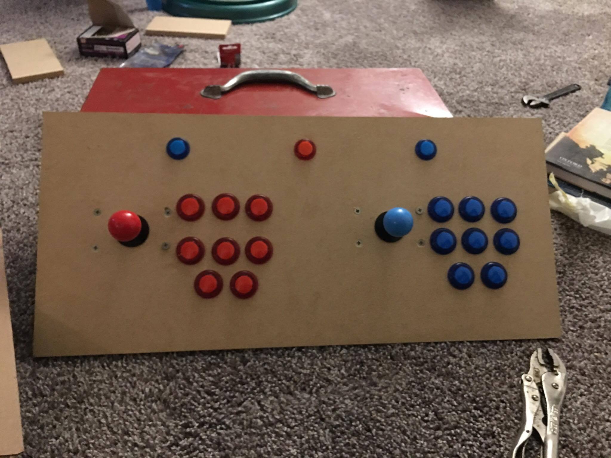
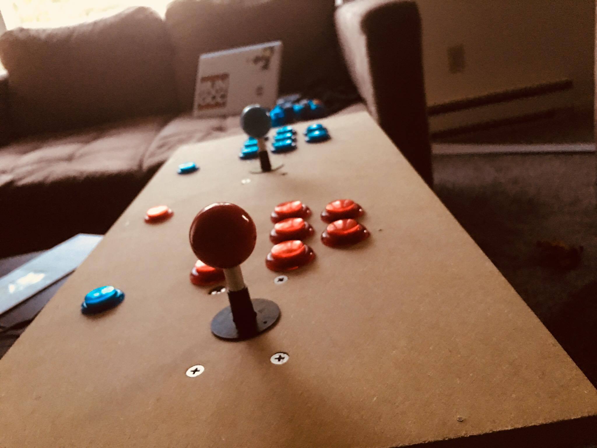
When all’s said and done, you should come away with a board that looks like this:
Without further ado, Let’s get started.
Trip to Home Depot (and an Amazon order)!
We need to gather some supplies from Home Depot and of course we need some arcade buttons and joysticks. I was thinking of adding a trackball, but I decided against it because I felt it would make the board to busy.
Arcade Buttons
For the arcade buttons, I went with these buttons from Amazon. I’m sure any arcade button set on Amazon would work, but I chose this one in particular because a) it lights up, and b) it has a relatively high rating with plenty of reviews. This set also comes with two USB encoders and two different colored buttons and joysticks, so you can play with two people. I also bought these other buttons for no other reason except it says coin and has player icons. I actually did not use these buttons in this project, though I may add them later.
Drill bit sizes
Arcade buttons come primarily in two sizes: 30mm and 24mm, and both of these kits use that size. In the USA, where I live, it is extremely difficult to find those exact size drill bits to use to cut the holes out. The next best thing is to get drill bits that approximate the proper sizes. For the 30mm holes, I used a 1 1/8” hole saw, and for the 24mm, I used a 15/16” spade tip drill bit. The 1 1/8 inch drill bit was the perfect size even though the box said that it cuts a 29mm hole. The 15/16 drill bit was good too, but it was a little small. I tried a one inch spade tip (on a test board) and that was a little too big for the 24mm buttons. I honestly felt as though I could accidently punch the buttons through the hole. So instead of sticking with the one inch holes, I used the 15/16 spade tip and I used some sandpaper to make the buttons fit. After a light sanding (I went around the hole maybe 4-6 times), the 24mm buttons fit, though they are snugger than the 30mm holes.
If you can find a 23 or 24 mm spade tip, hole saw, forstner, or other bit to drill clean holes, definitely use those. If you can’t find those, you can use the 15/16 inch bit and just sand a bit.
Wood
This is an important piece of the of the board. It is what is holding your buttons after all!
For this, I used this Medium Density Fiberboard from the home depot for $11. The 4ft X 8ft board is $15 so if you want that, you can go for it, but I have plenty of wood left over from the 2ft X 4ft board.
I picked 1/2 inch MDF board because it wasn’t as flimsy as the 1/4 inch board; I couldn’t just take thee wood and flex it. I thought it felt more sturdy. I also picked fiberboard because it is easier to paint and when you cut or drill, it leaves cleaner edges than plywood. You should also be careful when cutting or drilling this wood as it contains some pretty nasty chemicals. Definitely cut this outside, with a saw that has a vacuum attached, or use one of those dust masks.

Some Miscellaneous items
In order to mount my joysticks, I grabbed a eight of countersunk M8 X 25mm Machine screws with 8 M8 nylon lock bolts. I only grabbed the Lock bolts because those were the first bolts I saw that would work. I also grabbed some finishing nails (the nails with the smaller heads) and small screws to mount the the USB encoders.
Let’s Actually Start Building
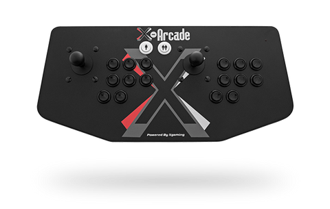
I drew my insperation from the X-Arcade Dual Joystick
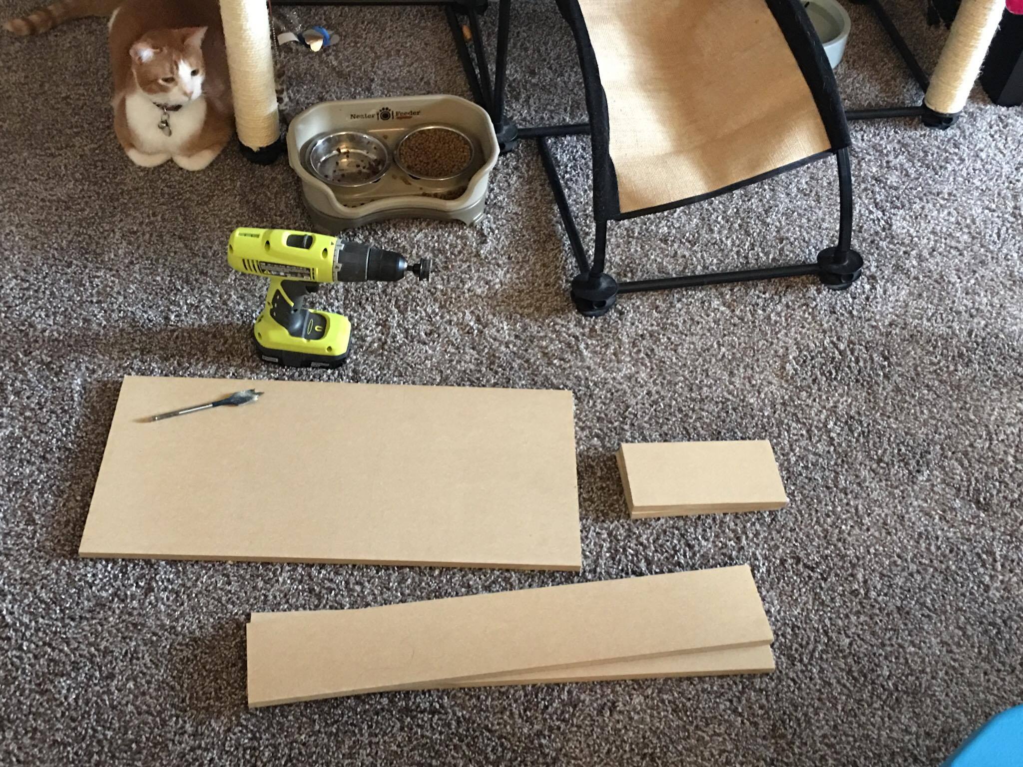
First cutting the wood.
I found this great forum post outlining their dimensions and decided to base my project off of that. I didn’t do the fancy cuts and angles because I don’t have easy access to a saw. So here is what I came up with:
- For the top piece (the piece with all the buttons), I made it 24 inches by 11 inches.
- for the two short sides, I made them 4 inches by 8inches.
- for the long sides, I made them 24 inches by 4 inches
- I wasn’t able to cut a bottom piece (due to lack of a saw), but the bottom piece would have been 24 inches by 9 inches.
Next step, Drilling the holes
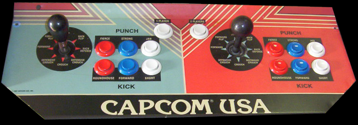
I wanted to get the feeling of an actual arcade machine. I figure the best way to do that was to make the board as symmetric as possible. First I made sure to draw lines right down the middle of the board, both lengthwise and widthwise. The width long line would be a starting position for player two’s controller, just like the edge is the starting position for player one’s controller. Then I put the line for the controller 4 inches from their respective edges (player two’s edge is the center line). After that, I measured 2 and a half inches from the joysticks, for where the buttons will begin. Next I spaced the buttons out at 4 cm each. Why the sudden change to metric? If you remember, the buttons are in metric so it was easier for me to do math when the button measurements are in metric. So I drew three new lines spaced 4 cm apart. But I have 8 big buttons! So I made two rows of 3 and one row of two.
The reason I did to rows of three is because I love Street fighter and the arcade game has two rows of three.
Next I made two lines, one above the lengthwise middle line and one below, both two centimeters from the middle line. Next, I made a line two centimeters from the bottom row and 4 centimeters from the middle button. When you are done with that step, you should have 10 places where lines intersect. 7 of those lines are where holes for the buttons and joystick will go. In the below picture, I circled where the buttons will go, and the joy stick goes where the lines intersect closest the edge.
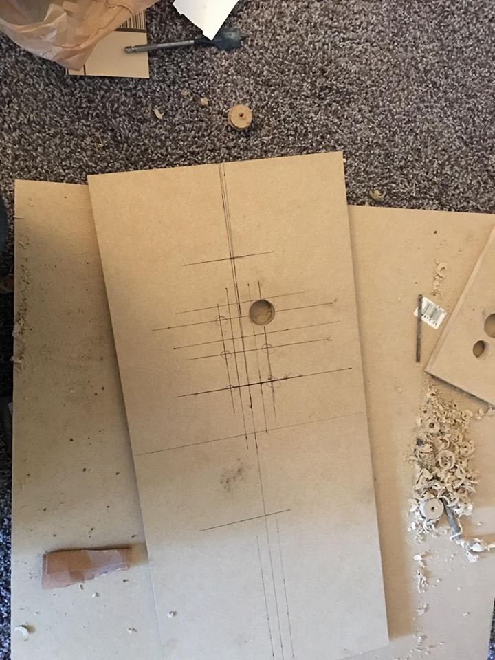
All of these holes need to be 1 1/8 inch, even the one for the joystick.
Next I drilled two holes in the base, both 1 and 1/8 inch. One hole is for side that will face your tv. This is where the cables for USB will run. I put this one smackdab in the middle of one of the 24 by 4 inch boards (centered at 12 inches and 2 inches). The other hole is for a button that will basically act as a select button for one of the players. I put this hole on one of the small 8 inch by 4 inch boards, so that it will be on the side. This button was put 4 inches from the back and two inches from the top. I did this so that it would be closer to the USB encoder.
The last set of holes I made were the three small 15/16 buttons at the top. I put one in the middle (12 inches from the edge), and 4cm from the other edge. I then put the other two holes 6 inches from this button (still 4cm from the edge).
Putting the buttons and Joystick.
After all of the button holes are drilled, you put in the buttons. The buttons I linked to above have plastic bolt like screws that you use to attach them. Slip the buttons in and then tighten the screws on. It should be pretty easy to do this.
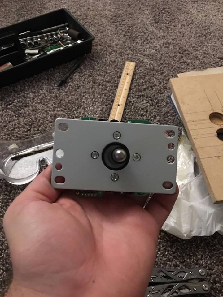
When that is done, it’s time for the Joystick. Make sure you measure the base plate of the joystick well. You need to drill four small holes for the bolts in order to mount the joystick.
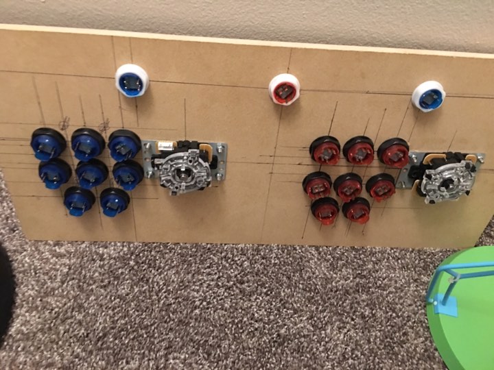
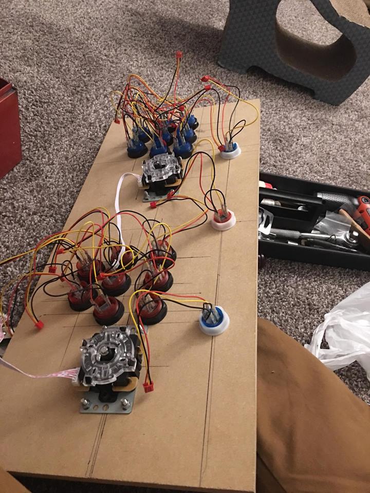
After that is all done, you should have something that looks like this:
Making the base
Next up is a really simple part, making the base. Honestly all I did here was use some wood glue and hammer in some finishing nails. When you are done, you will have this:
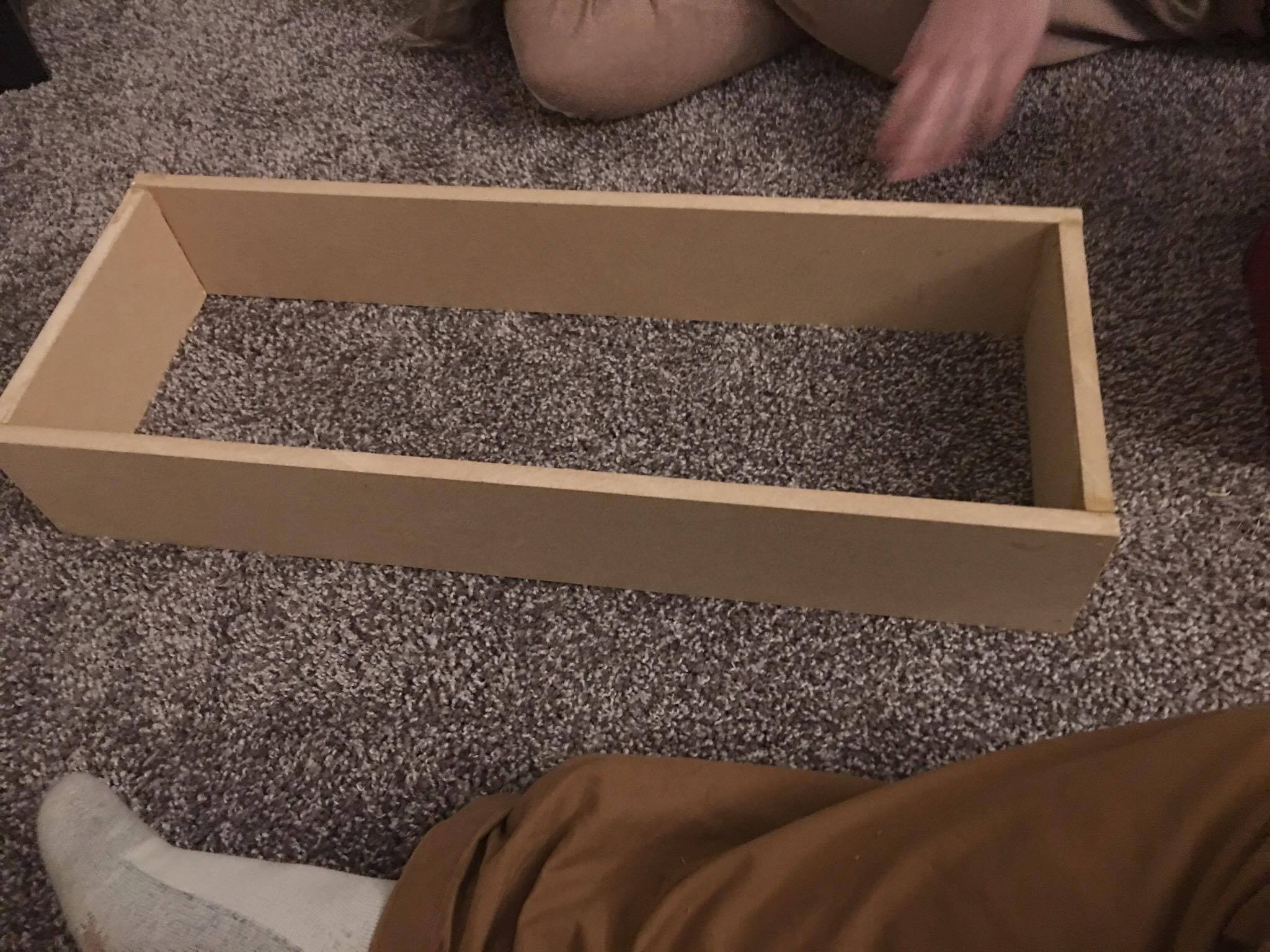
You’ll notice that my base doesn’t have the two holes. I took this picture before I drilled them. I don’t recommend doing that 🙂
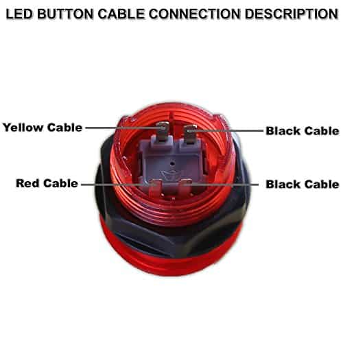
Saddle Up: the wiring
We are close to the finish line now! All we really need to do is wire it up. Wiring is really easy, especially because the buttons come with wire harnesses and instructions. First I put the wire on the buttons. It’s kind of hard to describe what wire goes where so here is a picture:
After all the buttons have wires, I would connect the USB encoder. You don’t have to worry where you put the buttons, because retro pie will ask you to map the inputs when you plug it in for the first time.
As a side note: I put the middle top button on player two’s encoder and the side button on player one’s encoder.
One last step!
Finally there is one last thing and that is attaching the arcade panel to the base. you can do this before or after wiring to be honest. All you really have to do is set the top board on top of the base and nail it down. I wouldn’t use screws as MDF splits easily and doesn’t hold screws really well.
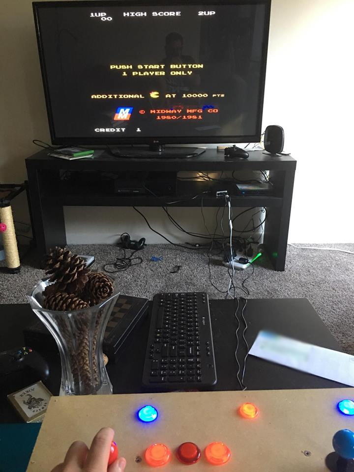
And that’s that!
You now have a working arcade controller that you can use to play whatever you want. You may want to add some things, like JoyStick extenders (I did) or a paint job. But you can really do whatever you want. This is an easy project so feel free to experiment!
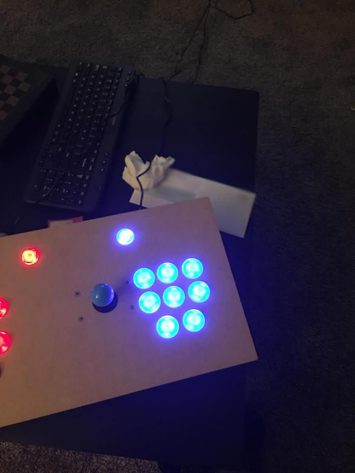
Extra photos
As always, if you have any questions or comments, let me know either through email, or in the comments below. Next week I am giving a talk at MSU’s Spartan hackers about building production code. Next week’s blog post will probably be about that!